Introduction
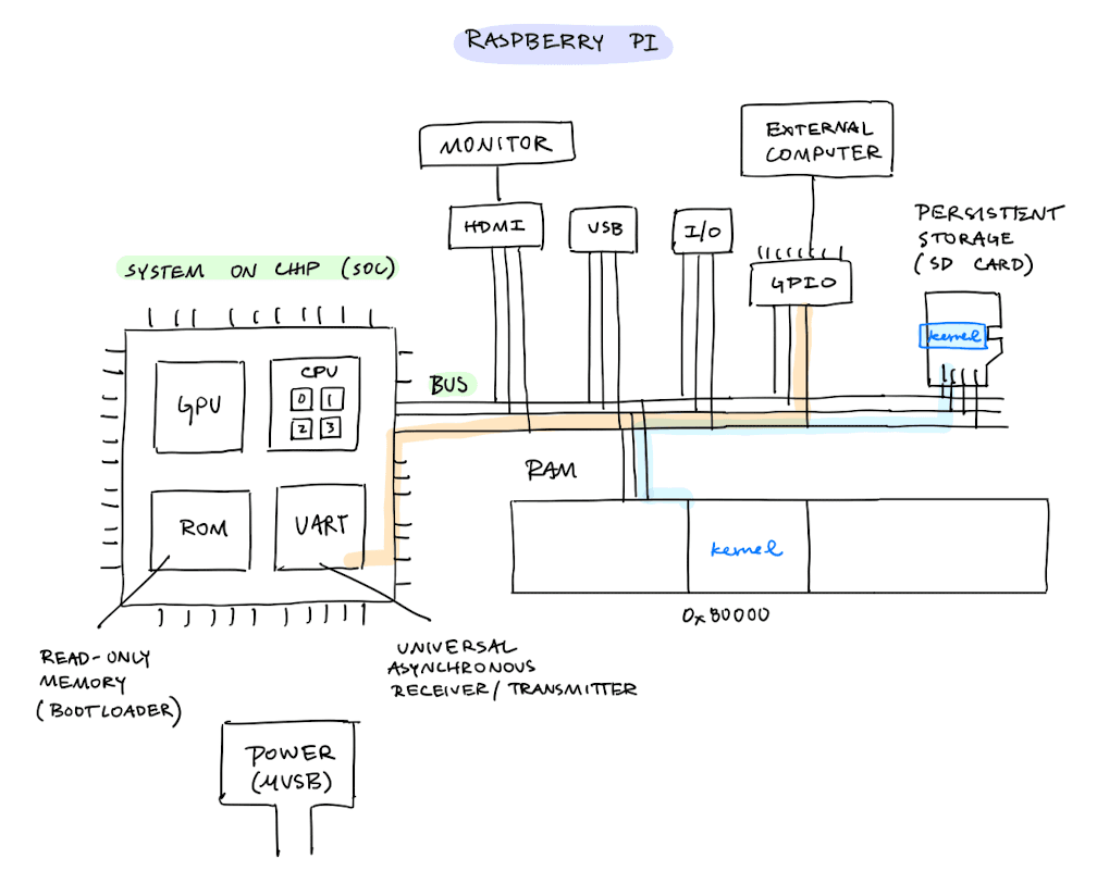
Raspberry Pi Architecture
Booting
Stages of Booting
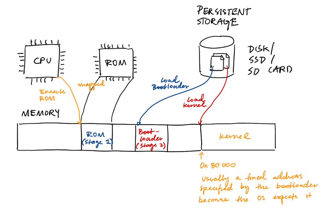
Booting proceeds in stages:
- Stage 0: CPU starts executing the ROM, which is mapped in RAM
- Stage 1: ROM loads the bootloader from persistent storage
- Stage 2: Bootloder loads the kernel ("image") into a fixed physical address
Boot code is written in assembly. (C assumes that there is a stack, which does not exist yet.)
Booting for Real
| Stage 0 | Stage 1 | Stage 2 | Stage 3 | |
|---|---|---|---|---|
| x86-64 | BIOS (ROM on flash) | Bootloader (MBR on disk) | Bootloader (disk) | OS (disk) |
| Apple Silicon | SecureROM (ROM on SoC) | iBoot1 (NOR flash) | iBoot2 (SSD) | MacOS (disk) |
| Raspberry Pi | Bootloader (ROM) | bootcode.bin (SD card) | start.elf, armstub.bin (SD card) | kernel8.img (SD card) |
x86-64
- BIOS stands for the Basic I/O System. It intializes hardware (RAM, hard disks, SSD, I/O devices). BIOS is configurable despite living on ROM because it is connected to a CMOS unit (flash) that has a small battery keeping it awake. Note that BIOS is a legacy boot method, and there is a new UEFI method.
- MBR stands for Master Boot Record, and it lives on the very first sector of the hard disk (block 0). When BIOS boots a hard disk, there is a bootloader on the MBR which just finds the next bootloader.
- Examples of "stage 2" bootloaders include GRUB (Linux), Windows Boot Manager, and U-Boot.
Apple Silicon
- For Apple, security is extremely important. Each stage of this boot process is cryptographically verified.
- NOR flash is a type of memory that allows a processor to read and execute code directly from the chip.
- iBoot1 initializes basic hardware.
- iBoot2 builds the Apple Device Tree (ADT) and passes it off to the kernel.
- To run Linux on Apple Silicon (Asahi Linux), it is possible to put m1n1 in Stage 3, which can then run U-Boot, GRUB, and then the Linux kernel.
Raspberry Pi
- Despite the fact that the bootup code lives in the SD card, a big chunk of it is run on the videocore GPU
- Many computers rely on binary blobs of firmware because a lot of device manufacturers do not want to share proprietary pieces of information
References:
- OSdev wiki page: System Initialization (x86)
- OSdev wiki page: MBR (x86)
- Asahi Linux blog post on the Apple Silicon bootup process
I/O Devices
Device Registers and Device Drivers
An I/O device will expose some kind of interface that allows us to control the device. These interfaces are commonly called device registers. If we change the bits in a device register, this will physically pull the pin HIGH or LOW and change the state of the device.
Device drivers are pieces of software that understands how to interact with the device and its device registers. Device drivers typically run inside of the kernel because interacting with devices is a privileged operation.
Memory-Mapped I/O
Question: How should the hardware communicate with a device?
There are two primary means of device communication:
- Explicit I/O instructions, such as
in <register>, <port>andout <register>, <port> - Memory-mapped I/O. The hardware makes device registers available as if they were memory locations. When the OS issues a read or write to the address, the hardware routes it to the device.
UART
UART stands for Universal Asynchronous Receiver-Transmitter. It is a hardware device that can communicate with other devices via a receiver and transmitter.
For example, we can write a program which writes and reads from the UART. The UART then forwards the writes to another device.
The UART needs to be modified so that it works with the device. It can be customized in terms of:
- Baud rate (bits/second)
- Parity